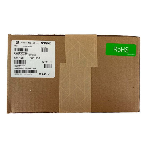
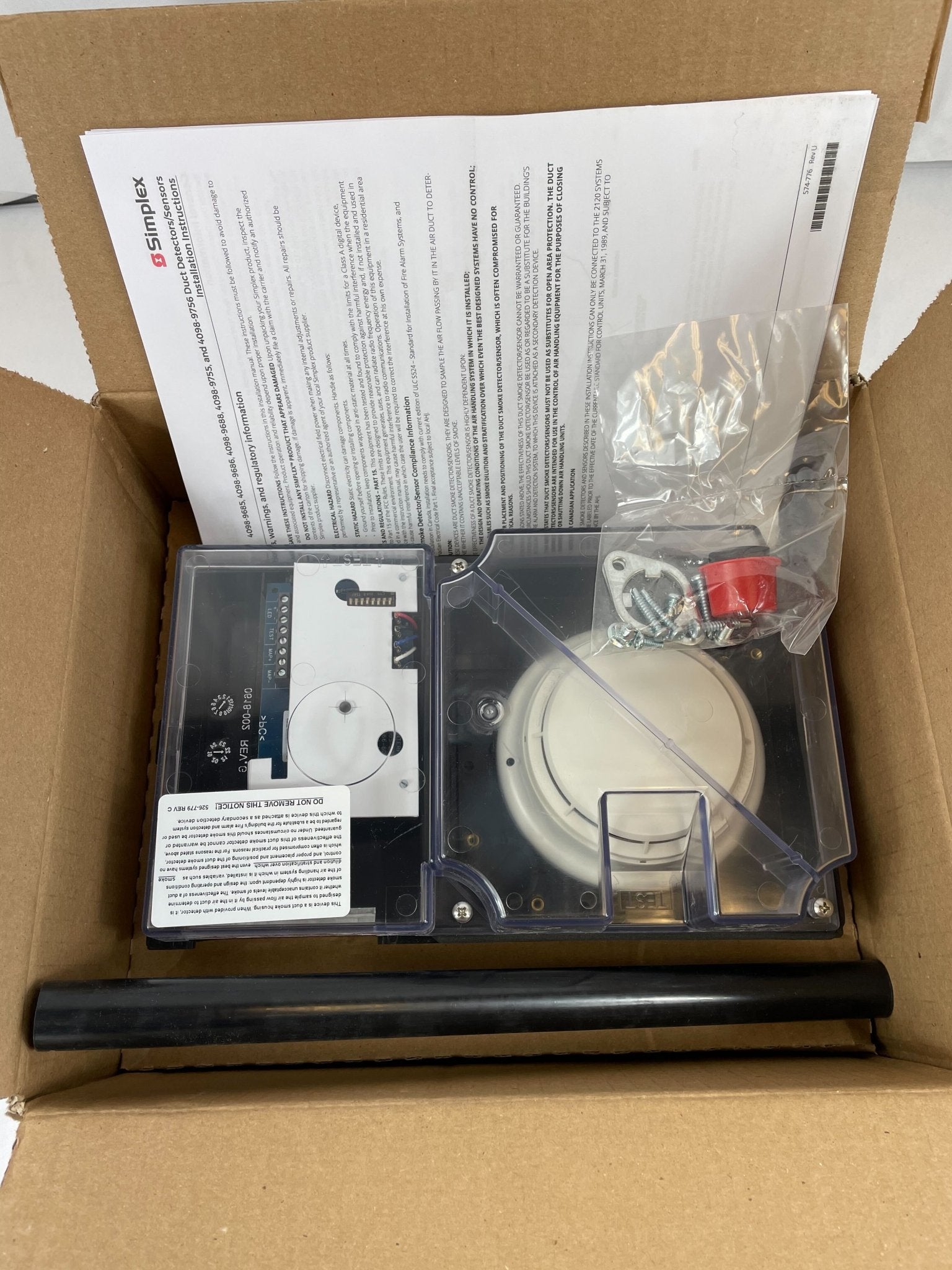
Simplex 4098-9755 — the basic TrueAlarm addressable duct smoke sensor housing, supplied with a factory-installed 4098-9714 photoelectric sensor and drawing all of its operating power from the IDNet or MAPNET II communications pair.
The 4098-9755 samples air from an HVAC duct through a sampling tube and returns it through the supplied exhaust tube, monitoring it for smoke with the internally mounted TrueAlarm photoelectric sensor. Analog values are transmitted digitally to the fire alarm control unit, which stores a running average per sensor and declares an alarm by comparing the present value against that average — the same software filtering that compensates for dust and component aging in the open-area TrueAlarm sensors, which matters in a duct because ducts are a relatively dirty environment. Duct applications typically use a less sensitive setting such as 2.5% per foot, but the full seven-level TrueAlarm range remains available per point. This is the no-relay model: it has no relay output and needs no separate 24 VDC supply, so it wires with the communications pair alone. Sampling tubes are ordered separately by duct width.
Specifications
| Device type |
Basic addressable duct sensor housing, no relay output; includes internally mounted 4098-9714 TrueAlarm photoelectric sensor and exhaust tube |
| Data communications and power |
IDNet or MAPNET II, auto-select, one address per housing; communications also supplies operating power |
| Sensor sensitivity range |
0.2% to 3.7% per foot of obscuration, selectable and monitored at the host control panel |
| Air velocity range |
300 to 4,000 ft/min (91 to 1,220 m/min) |
| Pressure differential |
0.015 to 1.55 in. of water (0.381 to 39.37 mm) between intake and exhaust tubes |
| UL listed temperature range |
32°F to 100°F (0°C to 38°C) |
| Operating temperature range |
32°F to 122°F (0°C to 50°C) |
| Storage temperature range |
0°F to 140°F (-18°C to 60°C) |
| Humidity range |
10% to 95% RH, non-condensing |
| Wiring connections |
Terminal blocks, 18 to 12 AWG (0.82 mm² to 3.31 mm²) |
| Housing |
Black ABS base with clear polycarbonate cover; sampling and exhaust tubes are black CPVC, sampling tubes pre-drilled |
| Minimum duct size |
8 in. (203 mm) square, or 18 in. (457 mm) diameter |
| Status indication |
Red alarm/trouble LED on the electrical interface board; pulses during polling, steady on for alarm, dirty or trouble |
| Remote indicator distance |
250 ft (76 m) maximum; remote alarm LED 1.2 mA, test station keyswitch 3.3 mA, neither affecting 24 VDC alarm current |
| Compatible control units |
4007ES, 4008, 4010, 4010ES, 4020, 4100, 4100ES, 4100E and 4120; also the 2120 CDT if configured for MAPNET II TrueAlarm operation |
| Listings |
UL listed to Standard 268A; ULC listed; FM approved; CSFM Listing 3240-0026.241; MEA (NYC) acceptance |
Installation notes
-
No relay output: if the design needs fan shutdown or damper control contacts driven from this point, the 4098-9756 with its supervised 4098-9843 relay output is the correct housing. The 4098-9755 cannot drive relays and does not accept the 4098-9843.
-
Sampling tube ordered separately: select by overall duct width — 4098-9854 up to 12 in., 4098-9855 for 13 to 23 in., 4098-9856 for 24 to 46 in., 4098-9857 for 46 to 71 in., 4098-9858 for 71 to 95 in. Cut the two smaller tubes 1/2 in. longer than the duct width and the three larger tubes 3 in. longer. Tubes install and service with the housing in place.
-
Orientation: mount at 90° to airflow for all orientations and do not mount on the bottom of the duct. Where the sampling tube is not vertical, FDI testing recommends positioning it horizontally in the upper half of the duct to account for stratification.
-
Airflow limits are a design constraint: the chosen location must deliver 300 to 4,000 ft/min and a 0.015 to 1.55 in. water pressure differential across the tubes.
-
Where to place it: downstream of filters to detect fires in the filters, in return ducts ahead of mixing areas, and upstream of humidifiers and cooling coils. Avoid outside air inlets, return air damper branch ducts and mixing areas, and points where comfort-control dampers closing would interfere with airflow.
-
Sensitivity: duct environments are dirty, so a less sensitive setting such as 2.5% per foot is typical; sensitivity is set at the panel, not on the device.
-
Duct detection is supplementary: Johnson Controls states that duct smoke detection signals the presence of smoke in the duct, does not replace open-area smoke detection requirements, and must never be regarded as a substitute for the building fire alarm and detection system.
-
Testing: the clear cover allows visual inspection, two test ports permit airflow measurement and aerosol injection with the cover in place, and a magnetic test area initiates an alarm at the housing.
-
Reference documents: installation instructions 574-776, plus NFPA 90A, NFPA 72 and the NEMA Guide for Proper Use of Smoke Detectors in Duct Applications.
Related models
-
4098-9756 — the same housing with a supervised output for up to fifteen 4098-9843 relays; requires separate fused 24 VDC
-
2098-9806 / 2098-9808 — remote test station with keyswitch and status LED, or remote red status/alarm LED, on a single-gang stainless steel plate
-
4098-9854 through 4098-9858 — sampling tubes in ascending lengths for duct widths from 12 in. to 95 in.
-
4098-9845 — NEMA 4X weatherproof enclosure for duct housings exposed to the weather (data sheet S4098-0032)
Specifications taken from the Simplex data sheet "TrueAlarm Analog Sensing — Addressable Duct Sensor Housings with TrueAlarm Photoelectric Sensor; Available with Multiple Relay Control," document S4098-0030-10 (11/2014). Manufacturer specifications are subject to change without notice.