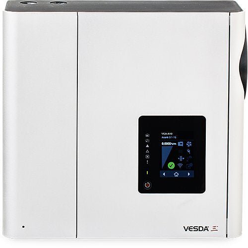
VEA-040-A10-UL — UL-listed VESDA-E VEA-40 addressable aspirating smoke detector with 40 microbore sampling points and a 3.5 in colour touch screen.
The VEA is the pinpoint-addressable member of the VESDA-E family. Instead of one pipe network reporting a single zone, it runs 40 individually addressed microbore tubes, each terminating in its own sampling point. The detector draws a combined sample from every point, filters it and analyses it in the laser detection chambers of the smoke sensor module; once a Fire 1 alarm is raised, a rotary valve sequentially scans the sampling locations to identify which one or more carry the event. If the system is in pre-alarm, a technician can trigger a smoke scan of all locations to investigate before an alarm confirms. A vacuum pump drives the network, giving usable detection times over long tube runs, and airflow monitoring detects breakage or blockage of individual points and tubes at set intervals. That combination suits spaces where knowing exactly where the fire is matters — healthcare, prisons, education, retail and electrical cabinets — and it allows testing and maintenance to be centralised at the detector rather than done room by room.
Specifications
| Order code |
VEA-040-A10-UL — VESDA-E VEA-040-A10-UL aspirating smoke detector with 3.5 in display |
| Sampling points |
40 addressable microbore tubes with individual sampling points |
| Supply voltage |
18 to 30 VDC (24 VDC nominal) |
| Maximum power |
25.6 W quiescent, 36.9 W alarm |
| Power consumption at 24 VDC (40 tubes) |
24.0 W quiescent, 36.9 W alarm; add 0.2 W with Ethernet enabled and 0.5 W with WiFi enabled |
| Peak current |
3.5 A |
| Dimensions (W x H x D) |
13.9 in x 13.2 in x 5.33 in (352 mm x 336 mm x 135.5 mm) |
| Weight |
22.2 lb (10 kg) |
| Operating conditions |
Ambient 32°F to 102°F (0°C to 39°C); sampled air 32°F to 122°F (0°C to 50°C); tested to 32°F to 102°F (0°C to 39°C); humidity 5% to 95% RH, non-condensing |
| Storage conditions |
Humidity dry (<95%); temperature 0°C to 85°C; must not be exposed to sunlight or other radiation sources |
| Microbore tube size |
Outer diameter 6 mm, inner diameter 4 mm — metric tubes only |
| Microbore tube length |
Up to 164 ft (50 m) per tube in Open Area; up to 328 ft (100 m) per tube in Special Application |
| Flow monitoring |
Single tube blockage and breakage detection |
| Detection chamber sensitivity |
0.020%/m to 16%/m (0.006%/ft to 4.88%/ft) |
| Fire 1 thresholds at the sampling point |
Standard 8.0%/m (2.5%/ft); Enhanced 4.0%/m (1.3%/ft); High 1.6%/m (0.5%/ft) |
| Relays |
7 programmable relays, contacts rated 2 A at 30 VDC (resistive), programmable to latch or not latch |
| General purpose inputs |
Two GPIs, one monitored and one unmonitored |
| IP rating |
IP40 (not UL tested) |
| Mounting |
Upright on a solid surface, with the steel support bracket or directly to the mounting surface |
| Cable access |
4 x 1 in (25 mm) cable entry ports |
| Cable termination |
Screw terminal blocks 0.2 to 2.5 mm² (24 to 14 AWG); use 18 AWG (1.1 mm²) or larger for power connections |
| Interfaces |
USB (Type 2), Ethernet (RJ45), WiFi 802.11 b/g/n, VESDAnet |
| Event log |
Up to 20,000 events on a FIFO basis with time and date stamp |
| Alarm and fault levels |
Four alarm levels (Alert, Action, Fire 1, Fire 2); two fault warning levels (Maintenance and Major Fault) |
| Field replaceable parts |
Filter, smoke sensor module, pump and rotary valve |
| Product listings |
UL, CSFM, FDA, FCC |
Installation notes
-
Fire 1 relay wiring to the panel is mandatory: the product guide requires the Fire 1 relay to be connected to the FACP for primary alarm reporting. Ethernet and WiFi are for configuration and secondary monitoring only, never the primary path.
-
Metric tube only: the sampling network uses 6 mm OD / 4 mm ID microbore tube. Imperial tube will not fit correctly — this is called out explicitly in the specification table.
-
Tube length depends on application class: 50 m per tube in Open Area, but 100 m per tube in Special Application. Designing to the 100 m figure in an open-area installation over-runs the listing.
-
Power wiring is sized separately from signal wiring: terminals accept 24 to 14 AWG, but power connections require 18 AWG (1.1 mm²) or larger. A 3.5 A peak during scan mode is what drives that.
-
Scanning happens after Fire 1: location identification runs once Fire 1 is raised. Before that, a manual smoke scan of all locations can be initiated from pre-alarm — the detector does not continuously address each point.
- IP40 is stated but not UL tested.
-
Sampling point part numbers are in a separate document — the guide refers to data sheet document 29730 for sampling points, microbore tube and tube accessories.
Related models
-
VEA-040-A00 — the same 40-point detector with an LED fascia instead of the 3.5 in display.
-
VEA-040-A10 — the non-UL 3.5 in display model; its data sheet publishes different figures (27 W quiescent and alarm, up to 100 m per tube without an application-class split) and a different approvals set including ULC and EN 54-20.
-
VER-A40-40-STX — VESDA-E VEA 40-Relay Local StaX, used to identify and signal fire source locations on a fire panel loop.
-
VSP-972 / VSP-971 / VSP-973 / VSP-974 — VEA filter, smoke sensor module, pump and rotary valve spares.
Specifications taken from the Xtralis (Honeywell) "VESDA-E VEA-040-A10-UL Product Guide," document 36401_A1, part number AD36401-000 (April 2021). Manufacturer specifications are subject to change without notice.