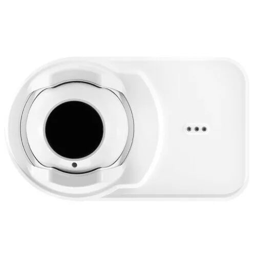
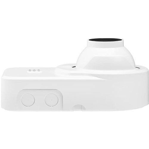
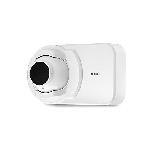
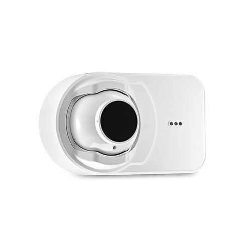
System Sensor OSI-R-SS — conventional 4-wire single-ended reflective imaging beam smoke detector. The combined transmitter/receiver unit and its reflector ship together, and only the detector end needs wiring, so a single conventional detector circuit covers spans up to 328 ft.
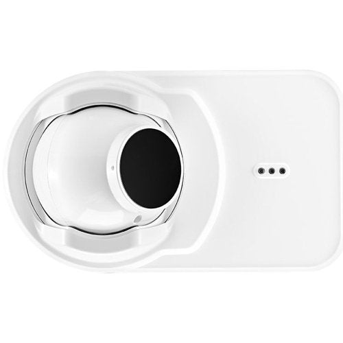
Projected beam detection suits large open volumes with high ceilings — warehouses, atria, gymnasia, historic halls — where spot detectors would be impractical or intrusive. The OSI-R-SS works on light obscuration: an infrared beam is thrown at a high-efficiency reflector and returned to a CMOS imager, and the drop in received signal when smoke crosses the path determines alarm. Where this unit differs from a traditional beam detector is the imager. Its wide 12° field of view automatically tracks the reflector, so ordinary building movement does not knock the beam out of alignment — the leading cause of false alarms and faults on conventional beams. Optical filtering, high-speed image acquisition and imaging algorithms also make it resistant to sunlight and other bright sources: saturated by light, the worst case is a trouble condition rather than a false alarm. Advanced smoke imaging distinguishes partial or sudden blockage by a foreign object from real smoke. Long range coverage from 16 to 328 ft is standard, with no separate long-range kit. Alignment is done through a movable “eyeball” lens assembly adjustable 50° horizontally and 20° vertically, guided by four directional LED arrows; when all four read green the lens is locked with a slide lever and a paintable cover secures it. Sensitivity threshold is set automatically from the size of the reflector seen in the field of view, and automatic drift compensation raises the threshold as dust accumulates on the optics. A built-in imager heater is standard.
Specifications
| Model |
OSI-R-SS (UL listed; OSI-RA-SS is the ULC version) |
| Type |
Conventional 4-wire single-ended reflective imaging beam smoke detector |
| Principle |
Light obscuration, infrared beam with CMOS imager |
| Protection range |
16 ft to 328 ft (5 m to 100 m) |
| Field of view |
12°, automatically tracks the reflector |
| Building movement tolerance |
±1° |
| Adjustment angle |
50° horizontal, 20° vertical |
| Sensitivity levels |
Level 1 25%, Level 2 30%, Level 3 40%, Level 4 50% — set automatically |
| Operating voltage |
10.2 to 32 VDC (12 or 24 VDC nominal) |
| Maximum standby current |
7 mA @ 32 VDC; 11 mA @ 24 VDC; 20 mA @ 12 VDC; 50 mA @ 10.2 VDC |
| Maximum alarm current (LED on) |
11 mA @ 32 VDC; 15 mA @ 24 VDC; 24 mA @ 12 VDC; 54 mA @ 10.2 VDC |
| Operating temperature |
UL listed for use from 32°F to 100°F (0°C to 37.8°C); application temperature range −4°F to 131°F (−20°C to 55°C) |
| Operating humidity |
0 to 95% RH, non-condensing |
| Detector dimensions |
6″ (152.4 mm) H × 10″ (254 mm) W × 4.5″ (114.3 mm) D |
| Reflector dimensions |
9.06″ (230 mm) H × 7.87″ (200 mm) W |
| Weight, installed |
2.48 lb (1.12 kg) |
| Weight, shipping |
3.91 lb (1.77 kg) |
| Terminals |
14 AWG (2.08 mm²), removable plug-in terminal blocks |
| Alarm indicator |
Local red LED and remote output |
| Trouble indicator |
Local yellow LED and remote trouble output |
| Normal indicator |
Local flashing green LED |
| Fault conditions |
Long-term drift reference out of 20% range, beam blockage, detector out of alignment, imager saturated |
| Test and reset |
Local alarm test and reset switches; remote test and reset with RTS151 or RTS151KEY(-A); uses OSID-R test filter |
| Spacing |
On smooth ceilings, 30–60 ft between projected beams and not more than half that spacing between a beam and a sidewall — see NFPA 72 (S524 in Canada) |
Installation notes
-
The UL listed temperature range is much narrower than the application range: UL listing covers 32°F to 100°F, while the published application range is −4°F to 131°F. For a listed installation, design to 32°F–100°F and consult the AHJ before relying on the wider figure — unheated warehouses and rooftop-adjacent spaces routinely fall outside the listing.
-
Current rises sharply as voltage falls: standby is 7 mA at 32 V but 50 mA at 10.2 V, and alarm is 11 mA at 32 V against 54 mA at 10.2 V. Calculate from the worst-case voltage at the end of the run, not from the nominal 24 V figure.
-
The imager heater needs its own supply: the built-in heater that prevents condensation on the optical surface requires an external power supply; it is not fed from the detector circuit. The separate BEAMHKR reflector heater kit draws up to 450 mA at 32 V (7.7 W at 24 V, 15 W at 32 V) and needs 15–32 V.
-
Sensitivity is automatic, not a dial: the detector selects its own optimum level from the apparent size of the reflector in its field of view. Do not plan on manually setting an obscuration percentage; verify the resulting level during commissioning.
-
Rigid mounting still matters: the imager tolerates ±1° of movement and tracks the reflector within its 12° field of view, but both detector and reflector must be on structure that will not flex beyond that. Mount to solid structure, not to suspended ceiling grid.
-
Keep the beam path clear: a full beam blockage produces a trouble, not an alarm. Allow for stored stock height, cranes, banners and seasonal decorations in the beam path, and keep the required clearance from the ceiling per NFPA 72.
-
Spacing and sidewalls: on smooth ceilings, beams are spaced 30–60 ft apart with no more than half that distance from a beam to a sidewall. Ceiling height, airflow and response requirements can change this — NFPA 72 governs.
-
Ground-level testing: pair with an RTS151 or RTS151KEY station so the electronic simulated smoke test and reset can be performed from floor level rather than from a lift. Functional testing uses the OSID-R test filter.
-
Single-ended wiring: only the detector end needs power and circuit connections. The reflector is passive, which is what removes the second cable run and second power supply that a two-ended beam system requires.
Related models and accessories
-
OSI-RA-SS — the ULC listed version of the same conventional imaging beam detector, reflector included
-
OSP-002 — laser alignment tool
-
OSP-004 — test filter, 10-pack
-
RTS151 — remote test station; RTS151KEY flush-mount test and reset station with key lock (UL); RTS151KEY-A ULC version
-
BEAMHKR — heater kit for the reflector, 15–32 V, 450 mA max at 32 V
-
6500-MMK — multi-mount accessory for ceiling or wall mounting with additional adjustment
Specifications taken from the System Sensor data sheet “OSI-R-SS, OSI-RA-SS Conventional Reflective Imaging Beam Smoke Detector,” document BMDS904-01 (1/16/2019). Manufacturer specifications are subject to change without notice.