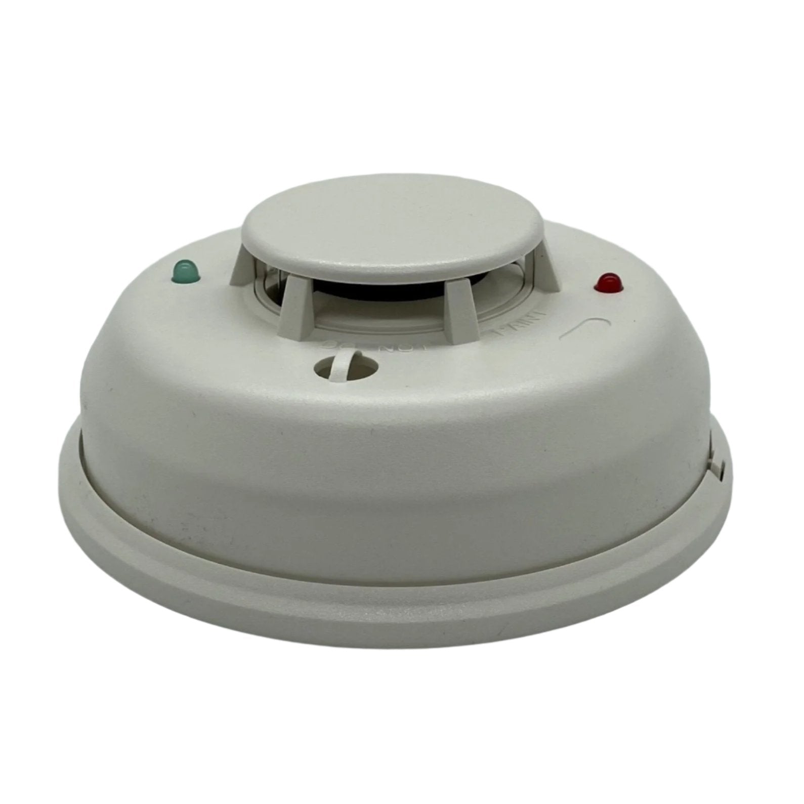
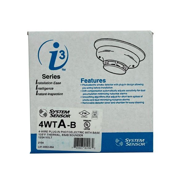
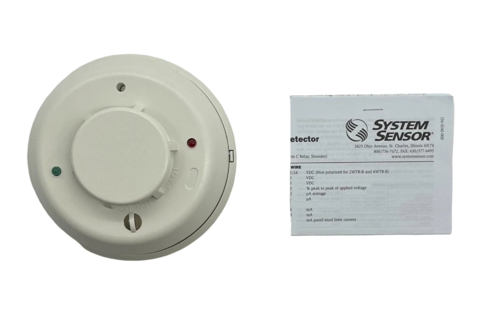
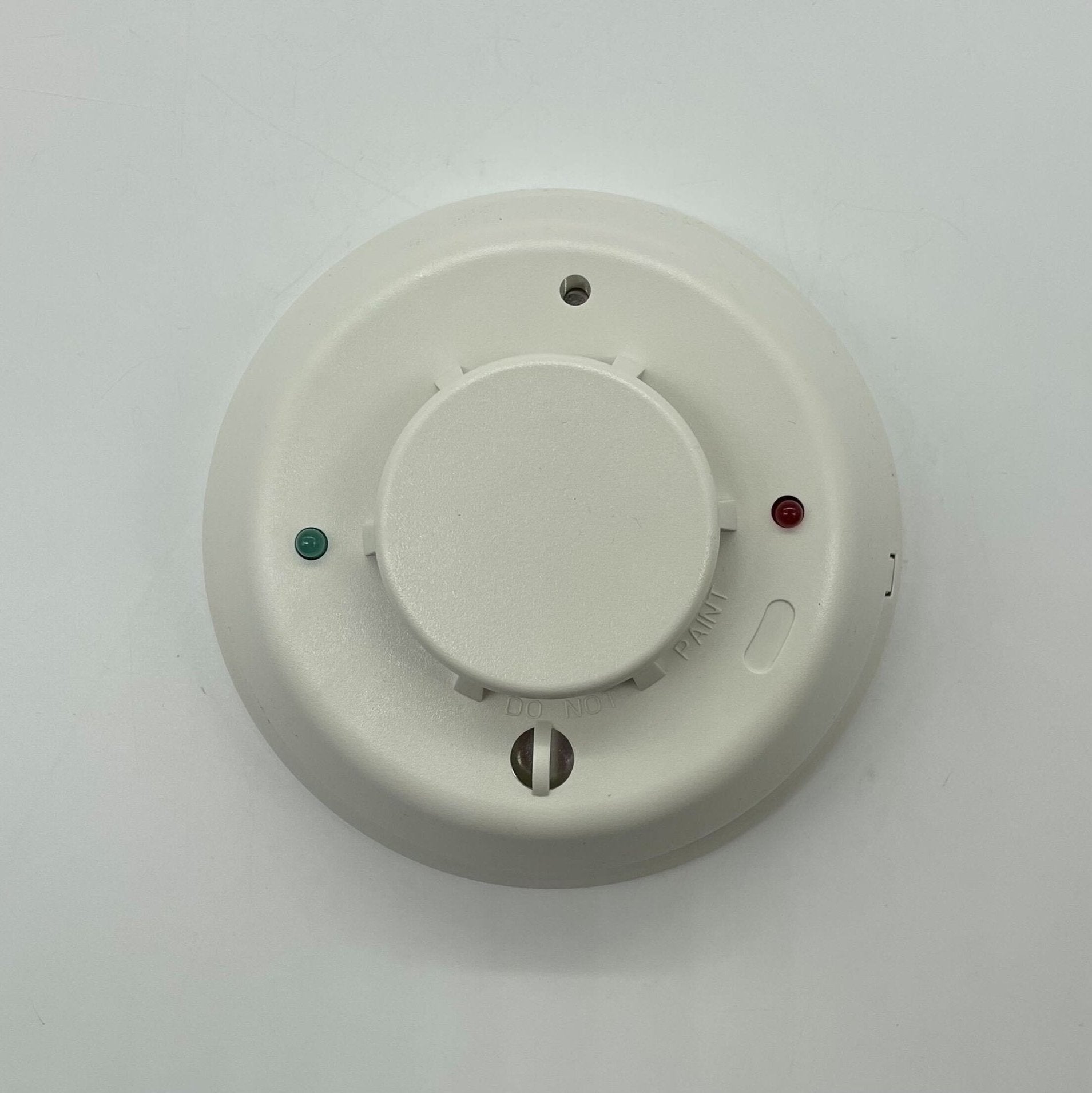
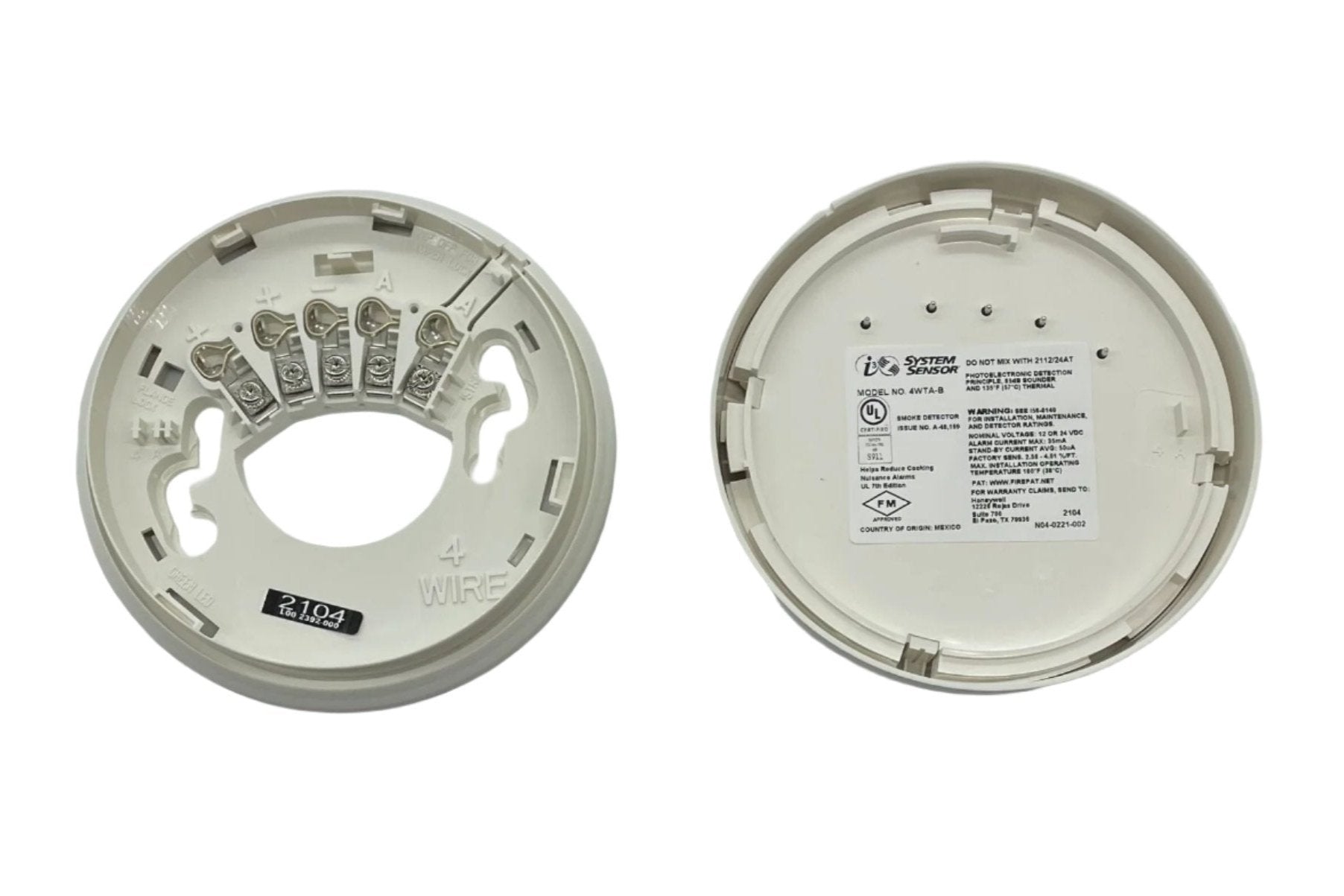
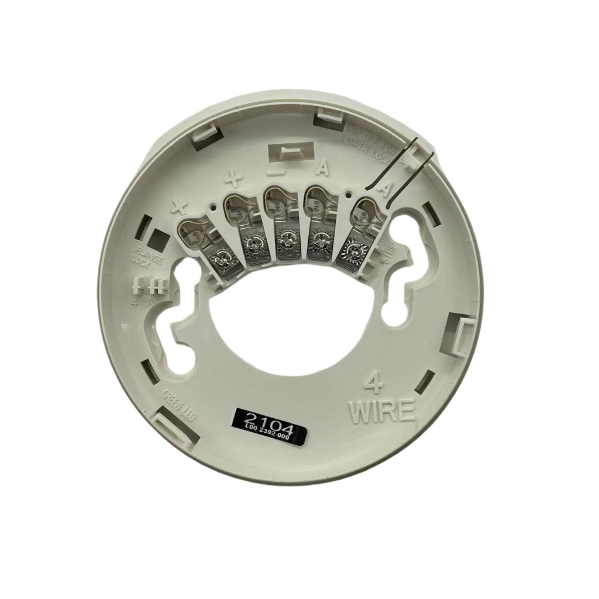
System Sensor 4WTA-B — conventional 4-wire i3 series photoelectric smoke detector with a 135°F fixed thermal sensor and a built-in 85 dBA sounder, supplied as a plug-in head with its mounting base included.
The 4WTA-B suits 4-wire installations that need local audible notification at the detector itself — sleeping rooms, apartments, small tenant spaces and any location where an occupant should hear the device that sensed the fire. It takes operating power from a separate supervised 4-wire power circuit and signals alarm through dry initiating contacts, so the panel sees a contact closure rather than a current change. The combination photoelectric and thermal sensing responds both to visible smoke and to a fixed 135°F heat threshold. Drift compensation and smoothing algorithms limit nuisance alarms from dust build-up and RF interference, and dual-color LEDs report power up, standby, out-of-sensitivity, freeze trouble and alarm. Head and mounting base ship together.
Specifications
| Model |
4WTA-B (i3 series, sounder option) |
| Detection |
Photoelectric smoke with thermal sensor |
| Wiring |
4-wire |
| Operating voltage |
12/24 V nominal, non-polarized; 4-wire range 10 V to 35 V |
| Maximum ripple voltage |
30% of applied voltage (peak to peak) |
| Standby current |
50 µA maximum average |
| Maximum alarm current |
35 mA |
| Alarm contact ratings |
0.5 A @ 30 V AC/DC |
| Sound pressure output |
85 dBA temporal tone |
| Sensitivity |
2.5%/ft. nominal |
| Thermal sensor |
135°F (57.2°C) fixed |
| Freeze trouble |
41°F (5°C) |
| Operating temperature |
32°F to 100°F (0°C to 37.8°C) |
| Operating humidity |
0 to 95% RH, non-condensing |
| Input terminals |
14–22 AWG, SEMS screws |
| Dimensions (including base) |
5.3″ (134 mm) diameter × 2.0″ (51 mm) height |
| Weight |
7.1 oz (200 g) |
| Listing |
UL 268, Fire Protection Signaling Systems |
| LED — power up |
Green and red both blink every 10 seconds, 80 second initial indication |
| LED — normal standby |
Green blinks every 5 seconds |
| LED — out of sensitivity |
Red blinks every 5 seconds |
| LED — freeze trouble |
Red blinks every 10 seconds |
| LED — alarm |
Red solid |
| Mounting |
3½″ octagonal, 4″ octagonal, single-gang or 4″ square back box with plaster ring, or direct to ceiling |
Installation notes
-
Sounder only — no Form C relay: the data sheet specifies the 4WTA-B as the photoelectric/thermal model equipped with a sounder. If the design also needs an auxiliary Form C relay, that is the 4WTAR-B, which draws 50 mA in alarm rather than 35 mA.
-
Budget 35 mA per head: the 4-wire power supply and its standby battery must carry 35 mA for every 4WTA-B expected to be in alarm simultaneously, plus 50 µA standby per head.
-
4-wire minimum voltage is 10 V: 4-wire i3 detectors operate from 10 V to 35 V. The 8.5 V minimum published for 2-wire i3 models does not apply here — check voltage drop at the end of long power runs against 10 V, not 8.5 V.
-
Remote maintenance signaling is a 2-wire feature: the 2W-MOD2 loop test/maintenance module serves 2-wire i3 detectors. Use the SENS-RDR to read this detector’s sensitivity in percent-per-foot obscuration.
-
Sounder synchronization: with an RRS-MOD reversing relay/synchronization module on the loop, all i3 sounders activate when any one detector alarms, their output is synchronized, and they can be silenced from the panel.
-
100°F ceiling: the thermal sensor limits the operating range to 32°F–100°F. Do not install in attics or unconditioned spaces that exceed that.
-
End-of-line supervision: as with any 4-wire detector, the power circuit must be supervised so that loss of detector power is annunciated as a trouble at the panel.
Related models
-
4WTAR-B — adds a Form C relay (2 A @ 30 V AC/DC) to the sounder; 50 mA alarm current
-
4WITAR-B — isolated thermal sensor with sounder and relay, for separate local and general alarm signaling; 50 mA
-
4WTR-B — 4-wire photoelectric/thermal without a sounder; 35 mA alarm current
-
2WTA-B — 2-wire equivalent with sounder; alarm current limited by the control panel
-
4WT-B — plain 4-wire photoelectric/thermal detector, no sounder; 20 mA at 12 V / 23 mA at 24 V
-
RRS-MOD — reversing relay/synchronization module; SENS-RDR sensitivity reader; RT removal tool; A77-AB2 retrofit adapter bracket
Specifications taken from the System Sensor data sheet “Smoke Detectors with Sounder and Relay Option,” document A05-0348-004 (6/09). Manufacturer specifications are subject to change without notice.