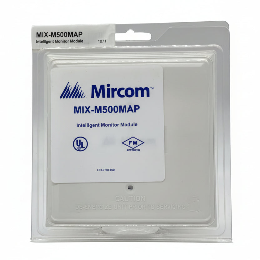
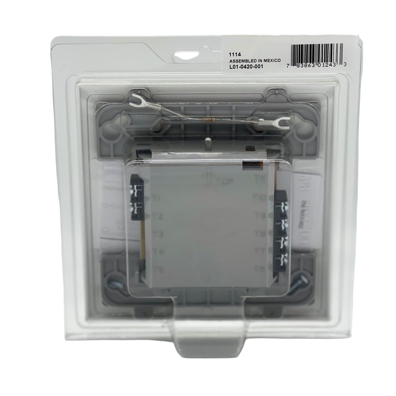
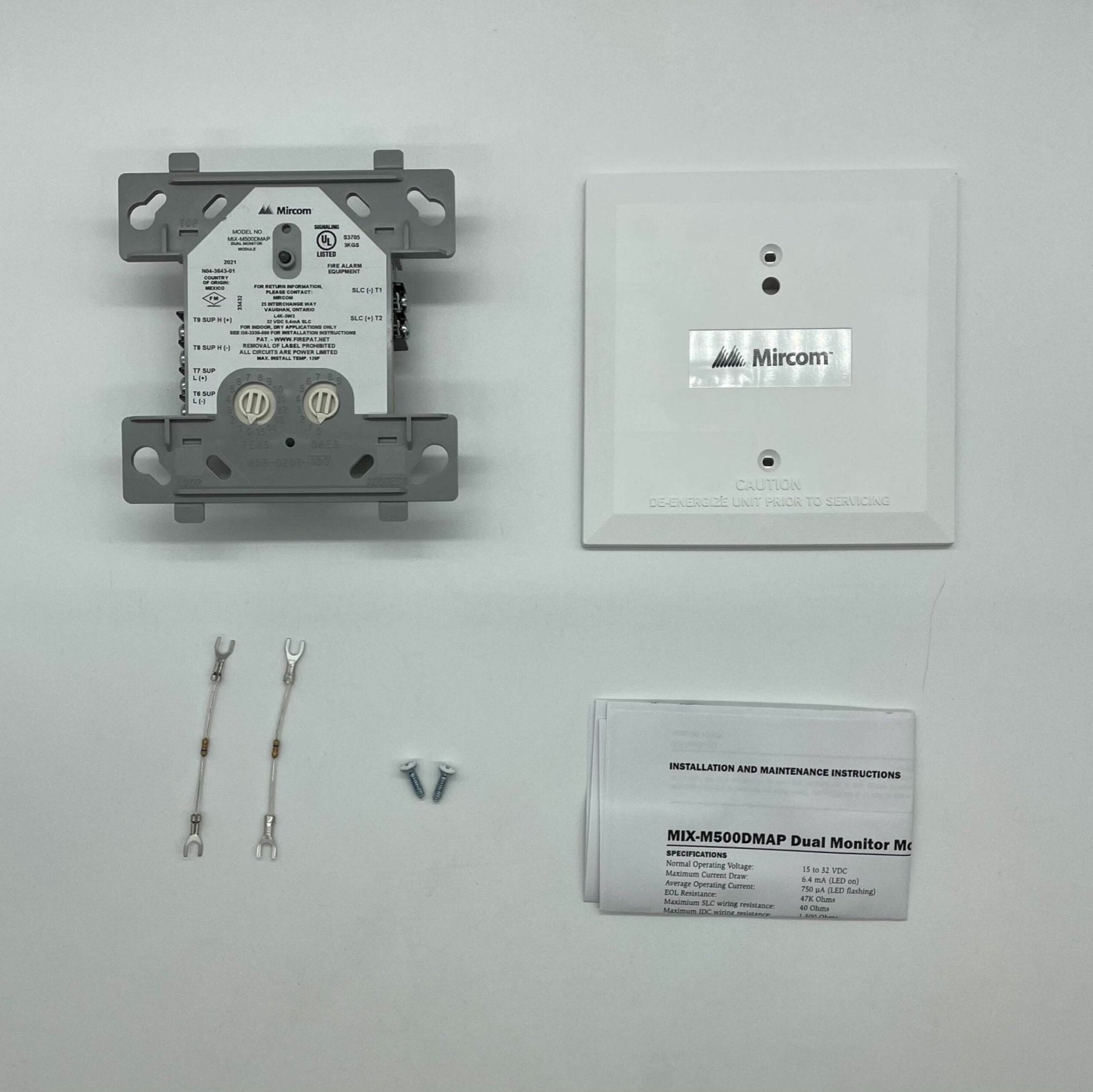
Mircom MIX-M500MAP — standard-size addressable monitor module supervising a circuit of dry-contact initiating devices on a Mircom Advanced Protocol loop.
A monitor module is how a normally open contact — a manual station, a waterflow or tamper switch — reports under its own address instead of disappearing into a shared conventional zone. Address is dialled on rotary decade switches, 01 to 159 in Advanced Protocol mode or 01 to 99 in CLIP mode.
- Supervises a Style D (Class A) or Style B (Class B) circuit, wired 2-wire or 4-wire fault tolerant
- Panel-controlled status LED indicator
- 15 to 32 V DC; 5.0 mA maximum alarm current with LED on, 400 µA average
- 47 kΩ end-of-line; IDC limited to 400 µA at 11 V, 40 Ω maximum wiring resistance
- Mounts to a 4 in. square box of at least 2 1/8 in. depth; SMB500 surface box available
- 4.5 × 4 × 1.25 in.; 32 to 120 °F
The MIX-M501MAP mini module is Class B only, has no panel-controlled LED and fits behind a device; the MIX-M502MAP is the zone interface for two-wire 24 V detectors on a 3.9 kΩ end-of-line; the MIX-M500X is the loop isolator.
Documents
FAQ
Can the MIX-M500MAP supervise a Class A circuit?
Yes. It provides either a 2-wire Style B (Class B) or a 4-wire fault tolerant Style D (Class A) initiating circuit for normally open contact devices.
What end-of-line resistor does it use?
A 47K ohm end-of-line resistor. The initiating circuit is limited to 400 µA at 11 VDC with a maximum of 40 ohms wiring resistance.
What box does it mount to?
A 4 in. square electrical box with a minimum depth of 2 1/8 in. Surface mount SMB500 boxes are available from System Sensor.
Can fire and supervisory devices share one module?
No. Mircom instructs not to mix fire alarm initiating, supervisory or security devices on the same module.